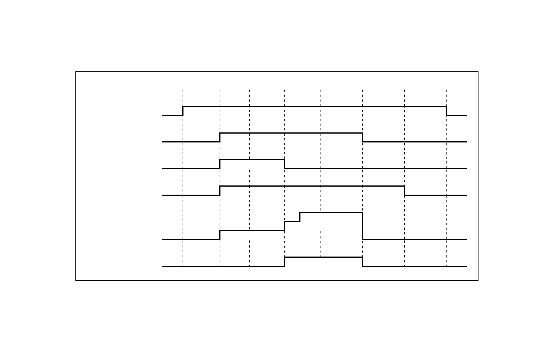
Ogólny schemat czasowy działania systemu powermax, Powermax generic timing chart – Hypertherm Powermax105 Rev.0 Instrukcja Obsługi
Strona 341
Advertising

12-3
Powermax Generic Timing Chart
Powermax Service Reference
Maximum 5 seconds
User set current
Transfer PA current
Pilot arc current
Transfer threshold: 1.6 A
PMX Timing Chart (1 of 1)
Pilot arc
Transfer
Steady state
Loss of start
Inverter output on
Transfer relay and LED on
Idle
Power off
Post flow
Power/Aux switch closed
Start LED on
Pilot arc IGBT gated
Gas control device LED on
Power up
Start
Ogólny schemat czasowy działania systemu Powermax
Advertising
Podręcznik ten jest związany z następujących produktów: